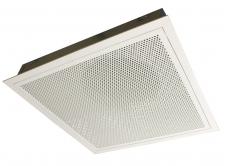
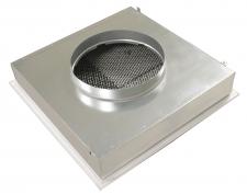
Air supply diffusers with adjustable 1- to 4-way pattern perforated plate for mounting in 600 x 600 mm system ceilings.
Explanation
PS/PPTMB = Diffuser type
200 = Diffuser size (connection diameter)
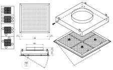
Dimensions
|
| 160 | 595x595 | 160 | | 200 | 595x595 | 200 | 250 | 595x595 | 250 | 315 | 595x595 | 315 |
Quick selection
|
| Q | Ak | 0.1457 | 0.1457 | 0.1457 | 0.1457 | |
| 150 | Vz | H= | 2.7 | 0.44 | 0.15 | 0.09 | | | | | | | | | | | H= | 3.2 | 0.17 | 0.1 | 0.07 | | | | | | | | | | | H= | 3.8 | 0.1 | 0.07 | 0.05 | | | | | | | | | | | Vk | 0.3 | | | | | X0.25 | 1.7 | | | | | Ps | 0.4 | | | | | Lw(A) | <20 | | | | | 200 | Vz | H= | 2.7 | 0.59 | 0.2 | 0.12 | | | | | | | | | | | H= | 3.2 | 0.22 | 0.13 | 0.09 | | | | | | | | | | | H= | 3.8 | 0.13 | 0.09 | 0.07 | | | | | | | | | | | Vk | 0.4 | | | | | X0.25 | 1.9 | | | | | Ps | 0.7 | | | | | Lw(A) | <20 | | | | | 250 | Vz | H= | 2.7 | 0.74 | 0.25 | 0.15 | 0.74 | 0.25 | 0.15 | | | | | | | | H= | 3.2 | 0.28 | 0.16 | 0.11 | 0.28 | 0.16 | 0.11 | | | | | | | | H= | 3.8 | 0.16 | 0.11 | 0.09 | 0.16 | 0.11 | 0.09 | | | | | | | | Vk | 0.5 | 0.5 | | | | X0.25 | 2.1 | 2.1 | | | | Ps | 1.1 | 1.1 | | | | Lw(A) | <20 | <20 | | | | 300 | Vz | H= | 2.7 | | | | 0.89 | 0.3 | 0.18 | | | | | | | | H= | 3.2 | | | | 0.33 | 0.19 | 0.13 | | | | | | | | H= | 3.8 | | | | 0.19 | 0.13 | 0.1 | | | | | | | | Vk | | 0.6 | | | | X0.25 | | 2.3 | | | | Ps | | 1.6 | | | | Lw(A) | | <20 | | | | 400 | Vz | H= | 2.7 | | | | 1.18 | 0.39 | 0.24 | 1.18 | 0.39 | 0.24 | | | | | H= | 3.2 | | | | 0.44 | 0.25 | 0.18 | 0.44 | 0.25 | 0.18 | | | | | H= | 3.8 | | | | 0.25 | 0.18 | 0.14 | 0.25 | 0.18 | 0.14 | | | | | Vk | | 0.8 | 0.8 | | | X0.25 | | 2.6 | 2.6 | | | Ps | | 2.8 | 2.8 | | | Lw(A) | | <20 | <20 | | | 600 | Vz | H= | 2.7 | | | | | | | 1.78 | 0.59 | 0.36 | 1.78 | 0.59 | 0.36 | | H= | 3.2 | | | | | | | 0.67 | 0.38 | 0.27 | 0.67 | 0.38 | 0.27 | | H= | 3.8 | | | | | | | 0.38 | 0.27 | 0.21 | 0.38 | 0.27 | 0.21 | | Vk | | | 1.1 | 1.1 | | X0.25 | | | 3.3 | 3.3 | | Ps | | | 5.2 | 5.2 | | Lw(A) | | | 25 | 25 | | 800 | Vz | H= | 2.7 | | | | | | | | | | 2.37 | 0.79 | 0.47 | | H= | 3.2 | | | | | | | | | | 0.89 | 0.51 | 0.36 | | H= | 3.8 | | | | | | | | | | 0.51 | 0.36 | 0.27 | | Vk | | | | 1.5 | | X0.25 | | | | 4 | | Ps | | | | 9.7 | | Lw(A) | | | | 34 | | 1000 | Vz | H= | 2.7 | | | | | | | | | | 2.96 | 0.99 | 0.59 | | H= | 3.2 | | | | | | | | | | 1.11 | 0.63 | 0.44 | | H= | 3.8 | | | | | | | | | | 0.63 | 0.44 | 0.34 | | Vk | | | | 1.9 | | X0.25 | | | | 4.8 | | Ps | | | | 15.6 | | Lw(A) | | | | 42 |
Symbols and specifications
- Q = Air Volume in m³/h
- Ak = Effective surface (free area) in m²
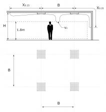
- B = Distance between diffusers in m
- H = Installation height of the diffusers in m
- Vz = Maximum velocity at the occupied zone regarding distance between diffusers and installation height in m/s
- Vk = Average effective velocity through the grill in m/s
- X0.25 = Throw length in m at an endvelocity Vt of 0,25m/s
- Ps = Static pressure loss given in Pa
- Lw(A) = Acoustic power in dB(A)
- The throw X0.25 is given at an end velocity of 0.25m/s for a smooth ceiling without any obstacles.
- The table values are given for the adjustable deflection plates set at its standard position to achieve an air flow pattern in 4 direction
- The values are given for isothermal supply air. Throw distances for cooling conditions at -11K can be calculated by deviding the X0.25 values with factor 1.1. For heating purposes at Dt of +11K a multiplier of 1.1 should be applied to the given X0.25 value.
- In order to achieve a high comfort level, selections can be made according to the maximal velocity at the occupied zone Vz. These values are given at distances between diffusers B and installation heights H. Velocities Vz lower than, or equal to 0,25m/s at the occupied zone are advised.
- The pressure losses Ps are given for grilles without damper of with fully opened damper.
- The acoustic power Lw(A) are given for grilles without damper of with fully opened damper without room attenuation. Acoustic powers below 20dB(A) are mentioned as "<20" in the tables.
- For all special requirements, please contact our engineering office.
Placement instruction
|