PRODUCTS


EShop-number
Password
Welcome to CAIROX BELGIUM
PS/PRN (RAL9016) • Diffusers for system ceilings
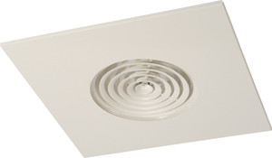
- Circular conical diffusers
- Square
- Aluminium & steel
- White, RAL 9016
- Fixed cones
Round ceiling diffusers with fixed diffusion rings in plate for system ceiling 600 X 600 for radial air discharge
Brand
- Cairox
Application
- For air supply and exhaust in ventilation and air conditioning systems
- Simple to integrate into suspended ceiling.
- Suitable for areas with high comfort requirements due to rapid reduction of temperature and air velocity because of an high induction rate.
Material
- Aluminium and steel combination
Colour
- Standard colour white, RAL 9016
- Other colours available upon request
Composition
- fixed diffusion rings
Mounting
- Fixing directly on the collar
Accessories
- Plenum box type RER-LB
- Insulated plenum box type RER-LB ISO
- Plenumbox connection valve type CRC
- Butterfly volume control damper for mounting on the neck of the diffuser, type DR
Text for tender
- The circular ceiling diffusers have fixed diffusion blades. They are made of steel and aluminium with white powdercoating finish RAL 9016 and supplied with a volume control damper in the plenum box.
- Cairox type PS/PRN+RER-LB
Order example
- PS/PRN, 200 + RER-LB + CRC 160
Explanation
PS/PRN = Diffuser type
200 = Diffuser size (Ø diffuser neck connection)
Accessories
RER-LB = Plenum box
CRC = Plenumbox connection valve
160 = Plenumbox connection diameter 160


Requesting information. Please wait a moment...