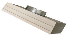
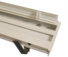
White linear slot diffusers with adjustable deflector for suspended ceilings
Always delivered with plenumbox
- ASM25-W 2 M L=595 + ASM25-CON
Explanation
ASM25-W = Diffuser type in white finish
2 = Slot quantity
M = With deflector
1500 = Length of diffuser
Accessories (optional)
PR25 2 1500 = Not-insulated plenum box for diffuser of 2 slots with a length of 1500mm
ASM25-CON = Connection piece to mount several diffusers in line
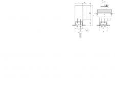
Dimensions
|
| PS/ASM25-W 1 M L=595 | 1 | 595 | 575 | 75 | 66 | 260 | 585 | 1x 160 | 25 | PS/ASM25-W 1 M L=1195
| 1 | 1195 | 1175 | 75 | 66 | 260 | 1185 | 1x 160 | 25 | | PS/ASM25-W 2 M L=595 | 2 | 595 | 575 | 119 | 110 | 300 | 585 | 1x 200 | 25 | PS/ASM25-W 2 M L=1195
| 2 | 1195 | 1175 | 119 | 110 | 300 | 1185 | 1x 200 | 25 | | PS/ASM25-W 3 M L=595 | 3 | 595 | 575 | 163 | 154 | 300 | 585 | 1x 200 | 25 | PS/ASM25-W 3 M L=1195
| 3 | 1195 | 1175 | 163 | 154 | 300 | 1185 | 1x 200 | 25 | | PS/ASM25-W 4 M L=595 | 4 | 595 | 575 | 207 | 198 | 350 | 585 | 1x 200 | 25 | PS/ASM25-W 4 M L=1195
| 4 | 1195 | 1175 | 207 | 198 | 350 | 1185 | 1x 250 | 25 |
Flow patterns deflectors
Quick selection
|
| Q | Ak | 0.0064 | 0.0128 | 0.0193 | 0.0257 | 0.0131 | 0.0263 | 0.0394 | 0.0526 | | 50 | Vk | 2.2 | 1.1 | | | 1.1 | | | | | X0,25 | 2.6 | 2.2 | | | 2.2 | | | | | Ps | 10 | 3 | | | 3 | | | | | Lw(A) | 28 | <20 | | | <20 | | | | | 100 | Vk | | 2.2 | 1.4 | 1.1 | 2.1 | 1.1 | | | | X0,25 | | 3.2 | 2.9 | 2.6 | 3.2 | 2.6 | | | | Ps | | 10 | 4 | 3 | 9 | 3 | | | | Lw(A) | | 30 | 21 | <20 | 29 | <20 | | | | 150 | Vk | | 3.2 | 2.2 | 1.6 | 3.2 | 1.6 | 1.1 | | | X0,25 | | 4.2 | 3.7 | 3.4 | 4.2 | 3.3 | 2.9 | | | Ps | | 22 | 10 | 5 | 22 | 5 | 3 | | | Lw(A) | | 39 | 30 | 24 | 39 | 24 | <20 | | | 200 | Vk | | | 2.9 | 2.2 | | 2.1 | 1.4 | 1.1 | | X0,25 | | | 4.5 | 4.1 | | 4 | 3.5 | 3.2 | | Ps | | | 18 | 10 | | 9 | 4 | 3 | | Lw(A) | | | 37 | 31 | | 31 | 21 | <20 | | 250 | Vk | | | 3.6 | 2.7 | | 2.6 | 1.8 | 1.3 | | X0,25 | | | 5.3 | 4.8 | | 4.7 | 4.1 | 3.7 | | Ps | | | 28 | 16 | | 14 | 7 | 4 | | Lw(A) | | | 43 | 36 | | 36 | 27 | 20 | | 300 | Vk | | | | 3.2 | | 3.2 | 2.1 | 1.6 | | X0,25 | | | | 5.5 | | 5.5 | 4.7 | 4.2 | | Ps | | | | 22 | | 22 | 9 | 5 | | Lw(A) | | | | 41 | | 40 | 31 | 25 | | 350 | Vk | | | | 3.8 | | 3.7 | 2.5 | 1.8 | | X0,25 | | | | 6.2 | | 6.2 | 5.3 | 4.7 | | Ps | | | | 31 | | 29 | 13 | 7 | | Lw(A) | | | | 45 | | 44 | 35 | 29 | | 400 | Vk | | | | | | | 2.8 | 2.1 | | X0,25 | | | | | | | 5.8 | 5.2 | | Ps | | | | | | | 17 | 9 | | Lw(A) | | | | | | | 38 | 32 | | 500 | Vk | | | | | | | 3.5 | 2.6 | | X0,25 | | | | | | | 7 | 6.2 | | Ps | | | | | | | 26 | 14 | | Lw(A) | | | | | | | 44 | 37 | | 600 | Vk | | | | | | | | 3.2 | | X0,25 | | | | | | | | 7.2 | | Ps | | | | | | | | 22 | | Lw(A) | | | | | | | | 42 |
Symbols and specifications
- Q = Air Volume in m³/h
- Ak = Effective surface (free area) in m²
- Vk = Average effective velocity through the grill in m/s
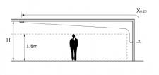
- X0.25 = Throw length in m at an endvelocity Vt of 0,25m/s
- Ps = Static pressure loss given in Pa
- Lw(A) = Acoustic power in dB(A)
- The horizontal throw X0.25 is given at an end velocity of 0.25m/s with all deflectors positioned for a maximal horizontal one-way throw installed in smooth ceiling without any obstacles.
- The values are given for isothermal supply air. Throw distances for cooling conditions at -11K can be calculated by deviding the X0.25 values with factor 1.1. For heating purposes at Dt of +11K a multiplier of 1.1 should be applied to the given X0.25 value.
- The pressure losses Ps are given for grilles without damper.
- The acoustic power Lw(A) are given for grilles without damper without room attenuation. Acoustic powers below 20dB(A) are mentioned as "<20" in the tables.
- For all special requirements, please contact our engineering office.
Placement instruction
|