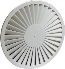
Swirl ceiling diffusers with high induction rate, consisting of a circular plate with multiple fixed blades arranged in a circular pattern, to be equipped with galvanized steel plenum box.
- RWR-FSA, 600/540 + RER-B 600 + CRC 250
Explanation
RWR-FSA = Diffuser type
600/540 = Diffuser size/swirl size
Accessories
RER-B = Type plenum box
600 = Size plenum box
CRC = Regulating valve for plenum box
250 = Plenum box connection diameter 250
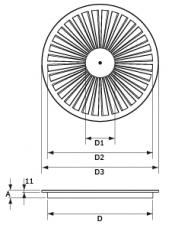
Dimensions
|
| RWR-FSA 300 | 238 | 100 | 236 | 296 | 41 | 28 | | RWR-FSA 400 | 338 | 150 | 336 | 396 | 41 | 30 | | RWR-FSA 500 | 438 | 150 | 436 | 496 | 41 | 32 | | RWR-FSA 600 | 538 | 150 | 536 | 596 | 22 | 32 | | RWR-FSA 625* | 538 | 150 | 536 | 621 | 22 | 32 | | * niet meer verkrijgbaar / n'est plus disponible / no longer available | | | | | | |
Quick selection
|
| Q | Ak | 0.01 | 0.016 | 0.033 | 0.049 | 0.049 | |
| 100 | | H= | 2.7 | 0.2 | 0.15 | 0.12 | 0.15 | 0.11 | 0.09 | | | | | | | | | | | Vz | H= | 3.2 | 0.15 | 0.12 | 0.1 | 0.11 | 0.09 | 0.07 | | | | | | | | | | | | H= | 3.8 | 0.12 | 0.1 | 0.08 | 0.09 | 0.07 | 0.06 | | | | | | | | | | | Vk | 2.8 | 1.7 | | | | | X0,25 | 1.2 | 0.8 | | | | | Ps | 3 | 2 | | | | | Lw(A) | <20 | <20 | | | | | 150 | | H= | 2.7 | 0.3 | 0.22 | 0.17 | 0.22 | 0.17 | 0.13 | 0.16 | 0.12 | 0.1 | | | | | | | | Vz | H= | 3.2 | 0.23 | 0.18 | 0.15 | 0.17 | 0.14 | 0.11 | 0.13 | 0.1 | 0.08 | | | | | | | | | H= | 3.8 | 0.18 | 0.15 | 0.13 | 0.14 | 0.11 | 0.1 | 0.1 | 0.08 | 0.07 | | | | | | | | Vk | 4.2 | 2.6 | 1.3 | | | | X0,25 | 1.8 | 1.3 | 0.9 | | | | Ps | 8 | 5 | 3 | | | | Lw(A) | 30 | 21 | <20 | | | | 200 | | H= | 2.7 | | | | 0.3 | 0.22 | 0.18 | 0.21 | 0.16 | 0.13 | 0.14 | 0.1 | 0.08 | 0.14 | 0.1 | 0.08 | | Vz | H= | 3.2 | | | | 0.23 | 0.18 | 0.15 | 0.16 | 0.13 | 0.11 | 0.11 | 0.09 | 0.07 | 0.11 | 0.09 | 0.07 | | | H= | 3.8 | | | | 0.18 | 0.15 | 0.13 | 0.13 | 0.11 | 0.09 | 0.09 | 0.07 | 0.06 | 0.09 | 0.07 | 0.06 | | Vk | | 3.5 | 1.7 | 1.1 | 1.1 | | X0,25 | | 1.9 | 1.2 | 0.7 | 0.7 | | Ps | | 9 | 4 | 2 | 2 | | Lw(A) | | 28 | <20 | <20 | <20 | | 250 | | H= | 2.7 | | | | 0.37 | 0.27 | 0.22 | 0.26 | 0.2 | 0.16 | 0.18 | 0.13 | 0.11 | 0.18 | 0.13 | 0.11 | | Vz | H= | 3.2 | | | | 0.29 | 0.23 | 0.19 | 0.2 | 0.16 | 0.14 | 0.14 | 0.11 | 0.09 | 0.14 | 0.11 | 0.09 | | | H= | 3.8 | | | | 0.23 | 0.19 | 0.16 | 0.16 | 0.14 | 0.12 | 0.11 | 0.09 | 0.08 | 0.11 | 0.09 | 0.08 | | Vk | | 4.3 | 2.1 | 1.4 | 1.4 | | X0,25 | | 2.3 | 1.6 | 1 | 1 | | Ps | | 13 | 7 | 3 | 3 | | Lw(A) | | 33 | 22 | <20 | <20 | | 300 | | H= | 2.7 | | | | | | | 0.31 | 0.23 | 0.19 | 0.21 | 0.16 | 0.13 | 0.21 | 0.16 | 0.13 | | Vz | H= | 3.2 | | | | | | | 0.24 | 0.19 | 0.16 | 0.17 | 0.14 | 0.11 | 0.17 | 0.14 | 0.11 | | | H= | 3.8 | | | | | | | 0.19 | 0.16 | 0.14 | 0.14 | 0.11 | 0.1 | 0.14 | 0.11 | 0.1 | | Vk | | | 2.5 | 1.7 | 1.7 | | X0,25 | | | 1.9 | 1.2 | 1.2 | | Ps | | | 10 | 4 | 4 | | Lw(A) | | | 27 | <20 | <20 | | 400 | | H= | 2.7 | | | | | | | 0.42 | 0.32 | 0.25 | 0.29 | 0.22 | 0.18 | 0.29 | 0.22 | 0.18 | | Vz | H= | 3.2 | | | | | | | 0.33 | 0.26 | 0.22 | 0.23 | 0.18 | 0.15 | 0.23 | 0.18 | 0.15 | | | H= | 3.8 | | | | | | | 0.26 | 0.22 | 0.19 | 0.18 | 0.15 | 0.13 | 0.18 | 0.15 | 0.13 | | Vk | | | 3.4 | 2.3 | 2.3 | | X0,25 | | | 2.7 | 1.8 | 1.8 | | Ps | | | 18 | 8 | 8 | | Lw(A) | | | 35 | 26 | 26 | | 500 | | H= | 2.7 | | | | | | | 0.52 | 0.39 | 0.31 | 0.35 | 0.27 | 0.22 | 0.35 | 0.27 | 0.22 | | Vz | H= | 3.2 | | | | | | | 0.41 | 0.32 | 0.27 | 0.28 | 0.22 | 0.19 | 0.28 | 0.22 | 0.19 | | | H= | 3.8 | | | | | | | 0.32 | 0.27 | 0.23 | 0.22 | 0.19 | 0.16 | 0.22 | 0.19 | 0.16 | | Vk | | | 4.2 | 2.8 | 2.8 | | X0,25 | | | 3.5 | 2.3 | 2.3 | | Ps | | | 27 | 12 | 12 | | Lw(A) | | | 40 | 31 | 31 | | 600 | | H= | 2.7 | | | | | | | | | | 0.43 | 0.32 | 0.26 | 0.43 | 0.32 | 0.26 | | Vz | H= | 3.2 | | | | | | | | | | 0.34 | 0.27 | 0.23 | 0.34 | 0.27 | 0.23 | | | H= | 3.8 | | | | | | | | | | 0.27 | 0.23 | 0.2 | 0.27 | 0.23 | 0.2 | | Vk | | | | 3.4 | 3.4 | | X0,25 | | | | 2.9 | 2.9 | | Ps | | | | 17 | 17 | | Lw(A) | | | | 37 | 37 | | 700 | | H= | 2.7 | | | | | | | | | | 0.5 | 0.38 | 0.31 | 0.5 | 0.38 | 0.31 | | Vz | H= | 3.2 | | | | | | | | | | 0.4 | 0.32 | 0.27 | 0.4 | 0.32 | 0.27 | | | H= | 3.8 | | | | | | | | | | 0.32 | 0.27 | 0.23 | 0.32 | 0.27 | 0.23 | | Vk | | | | 4 | 4 | | X0,25 | | | | 3.5 | 3.5 | | Ps | | | | 24 | 24 | | Lw(A) | | | | 41 | 41 | | | | | | | | | | | | | | | | | | | | |
Symbols and specifications
- Q = Air volume in m³/h
- Ak = Effective surface (free area) in m²
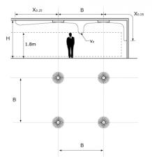
- B = Distance between the diffusers in m
- H = Installation height of the diffusers in m
- Vz = Maximum velocity at the occupied zone according to distance between the diffusers and installation height in m/s
- Vk = Average effective velocity through the diffuser in m/s
- X0.25 = Throw length in m at an end velocity Vt of 0,25m/s
- Ps = Static pressure loss given in Pa
- Lw(A) = Acoustic power in dB(A)
- The throw X0.25 is given at an end velocity of 0.25m/s for a smooth ceiling without any obstacles.
- The values are given for isothermal supply air. Throw distances for cooling conditions at -11K can be calculated by dividing the X0.25 values with factor 1.1. For heating purposes at Dt of +11K a multiplier of 1.1 should be applied to the given X0.25 value.
- In order to achieve a high comfort level, selections can be made according to the maximal velocity at the occupied zone Vz. These values are given at distances between diffusers B and installation heights H. Velocities Vz lower than, or equal to 0,25m/s at the occupied zone are advised.
- The pressure losses Ps are given for diffusers without damper of with fully opened damper.
- The acoustic power values Lw(A) are given for diffusers without damper of with fully opened damper without room attenuation. Acoustic powers below 20dB(A) are mentioned as "<20" in the tables.
- For all special requirements, please contact our engineering office.
Placement instruction
|